Description
As part of the Advanced Product Design class, in a team of 4 students, we were tasked with designing and prototyping a workout equipment focused on the upper body utilizing a cranking arm movement.
Contributions
-
Problem definition and first requirements
-
Market Research, MRD, PRD creation
-
Ideation and Concept generation
-
Prototyping and PoC device
-
Final design - CAD
Identification
Before defining our product, there were key questions to be answered. We created a survey for gym goers, gym owners and professionals, medical practitioners and further looked into existing products focused at upper body work-outs. Findings from this research helped us identify key elements to be targeted through our product:
-
Target Market: Performance and Strength Enhancement against Rehabilitation. This was adopted citing the market size of the strength and endurance building market, in addition to the increased home workout trend during the pandemic
-
Versatility: The upper body consists of a variety of muscle groups, and the general gym goer preferred to be able to exercise multiple muscle groups with the same equipment
-
Space Efficacy: While gym owners were more forgiving on space constraints, the home users were specific about being able to stow the equipment into a minimal footprint when not in use
-
Serviceability: This was a multi-faceted requirement that translated itself into design complexity as well assembly. The ideal product would be self assembled and serviceable for general failures directly by the end user
-
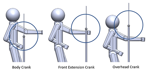
Standing workout - Unique and compelling for upper-body equipment
-
Levels of adjustability - Accommodate all types of users
Ideation
Resistance Mechanism
Several types of resistance mechanisms were ideated upon, keeping in mind simplicity and minimum number of total components. These included designs based on tension cables, compliant members, springs and resistance wheels.


Concept Sketches
Refining and Development
-
The compliant resistance mechanism was found to suit best the underlying theme of minimum parts and simplistic design.
-
To test out feasibility of this design, a quick mockup was created using off-the-shelf components and basic user testing was performed.
-
This design was then further developed with different compliant member materials, component sourcing and final PoC prototype creation.


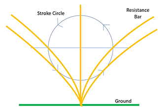
Stroke Cycle
Final Concept Sketch

Mock-Up
Product Development and Final Design
A user journey using the CoRo was created. It helped us identify key elements to consider while defining product features and subsystems.
.jpg)
User Journey Map
For the resistance mechanism, based on high strength and stiffness requirements, using the Ashby Plot, we identified using samples from the polymer and the metals groups. Tests were conducted using aluminum and steel rods, along with PVC pipes. Based on qualitative analysis of resistance provided, the aluminum rods were selected for final demonstration.

Ashby Plot (E vs. 𝛔)
Testing with PVC Pipe

Testing with Al Rod
Final Design


Resistance Adjustment
-
Soft Handle Bars: User touchpoint, light grip, fixed
-
Rigid Upright: Pressed to fit into base mat
-
Upright Swivel: Screwed into the rigid upright, easy to remove
-
Handle Slide Limiters: Screwed collars to prevent the handlebar from sliding across the upright swivel
-
Handlebar- Compliant Swivel: Push fit, plastic on metal, easy to disengage
-
Resistance Change Sleeve: Easily screwed on to the complaint mount
Functional Versatility


Fitness Tracking
Through Motion Tracking with Smartphone

-
Base
-
Compliant mount
-
Upright mount
-
Compliant beam.
-
Upright beam
-
Handle bar
-
Footboard
-
Resistance clamp
Final Demo