Description
Team Knox is the off-road racing team at IIT Roorkee. We participate in the all-terrain vehicle race competition BAJA SAE India held annually at Indore, Madhya Pradesh.
I worked with Team Knox in the powertrain engineering sub-group.
Together, we came up with 2 major projects for our design:
1. Overhauled powertrain cradle design
2. Custom sequential gearshift mechanism for driving modes

Bruizer - Our ATV
Contributions
-
Layout design concepts and selection
-
Component design and manufacturing
-
PVC prototype for fit and accuracy
-
Replication on steel tubes, welding
Powertrain Cradle Design
Problem and Inspiration
Teams competing at BAJA SAE are all supplied with the same engine to work with on their vehicle entries. Hence, transmission efficiency and powertrain design become critical towards getting a competitive edge.
Popularly, the continuously varying transmission (CVT) is used by many competing teams as it removes the need for frequent shifting of gears along undulated terrain, preserving vehicle momentum and removing risk of stall.
However, unlike geared transmissions, the CVT uses a belt to transmit motion between the engine and dependents. Being mounted on flexible pads to reduce vibration, we found that the belt tension between the driving and driven shafts is tough to maintain, leading to loss in power.
Serviceability of the buggy is also an important criterion in the eye of the competition as there are many sources of failure and breakdown given the uncertain environmental conditions of the event.
It was owing to both these considerations that we came up with the idea of mounting the engine and dependent gearbox together through a solid mount, which would then be installed into the vehicle separately.
Ideas and Advantages


Engine
CVT
Dependent Gearbox
There were three main components in the powertrain. The CVT connected the engine to the dependent gearbox, and dictated the center distance between the shafts to be 10 inches.
Accordingly, two types of layouts were imagined, each with specific advantages and demerits.

Vertical Layout
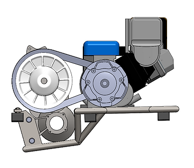
Horizontal Layout
While the vertical layout would help create a more compact design and allow for higher ground clearance and shorten the rear end of our buggy, the horizontal layout helped us reduce the elevation of our assembly and thus reduce risk of toppling and improve handling.
The horizontal layout was selected prioritizing the safety and robustness of our car for challenging terrain.

Assembled View
The impact of this addition was multi-fold. It provided us further advantages like:
1. Reduced vibrations transmitted from the cradle into the vehicle
2. Vibrational frequency range of the powertrain was brought down due to increased lumped mass of incited vibrations, thus helping avoid resonance with the vehicle frame and components.
3. Serviceability was greatly improved as the cradle could be plugged out of the vehicle directly for repair and rework on tight-reach spaces.
Shift System Design
Problem and Inspiration
Pairing the CVT to the engine allowed for a singular performance characteristic for the powertrain. In the past experience with the event conditions, CVTs often allowed high power utilization over continuous stretches and help achieve highest allowed vehicles speeds. However, the performance over steep inclines is usually compromised with CVTs and cannot be overcome without reducing top vehicle speed.
To overcome this, we used 2 different final reduction ratios through a 2 speed gearbox attached to the CVT. Where one provided race speed combo, the higher drive ratio would provide a 'hill-climb' mode of performance.
This called for the need of a shift system between the two drive modes.
The dependent gearbox was chosen keeping manufacturing and financial constraints in mind. We chose a 4 speed gearbox from a three wheeled load carrier. We modified the main shaft and removed the unnecessary two gears.
For the shift system, we conceptualized designs inspired from rotary cams used in motorbike gearboxes. There were two parallel cam profiles and a follower pin which was sandwiched between them. Rotation of the cams would provide transverse motion of the selector pin in the main shaft.

Main Shaft
Selector
Selector Guide
Rotary Cam
Exploded View
Layout Design
We designed rotary cams to be retro-fitted onto the main shaft of the gearbox which allowed for Neutral, High and Low gear configurations through equal rotations.
This was successfully installed with a tool ratchet based gear shift lever in the driver cabin.
With the hill-climb mode, we successfully completed the hill climb event of the race.

Upper Cam
Lower Cam
Selector Pin
